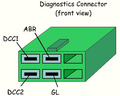
Reading Mazda RX7 86-88 Error Codes

(Original article mirrored from:  http://www.teamfc3s.org/info/articles/errorcodes/main.html     -RETed)

FORWARD


TABLE OF CONTENTS

TABLE OF FIGURES AND TABLES


INTRODUCTION


THE DIAGNOSTIC CONNECTOR


The diagnostic connector 
 
Signal        Name  Wire Colors  Source  Comments 
DCC1  Digital Code Checker 1      Yellow/Black     ECU pin 1A     open collector    
DCC2  Digital Code Checker 2  Yellow/Red  ECU pin 1B  open collector 
GL  Green Lamp  Yellow  ECU pin 1D  open collector 
ABR  Air Bypass Relay  Black/White  ABR  +12V supply 

Diagnostic Connector signals 
 
 
The Diagnostic Connector signals 

MONITORING THE SIGNALS

Tester components (Radio-Shack components are shown)

 
Schematic diagram of a LED assembly with protection for reverse voltage 

 
    1. Connect together the two anodes to a spade (use a crimping tool if you have one) . This will be ABR lead. 
    2. Connect each of the cathodes to a spade. These leads will be DCC1 and DCC2 respectively. 


    The following picture shows how the built tester looks like. If you like, you can install the two LED assembly in a small plastic box (also available from Radio Shack): 

 
The complete tester
 
Connecting the tester 

INTERPRETING THE SIGNALS


DOCUMENT MAINTENANCE