
|
|

|
Turbonetics T04B 60-1 This is a very popular turbo for the 13B. Notice how the "box" lands almost in the center of the concentric rings of the efficiency plateaus. One big thing missing is the efficiency plateau ring numbers, so we have no clue how efficienct the turbo is; this basically makes the compressor map useless. The "box" is clearly away from the surge limit line. Through experience, this compressor is good for 400hp at the wheels on a DynoJet at around 18psi. |
 |
|
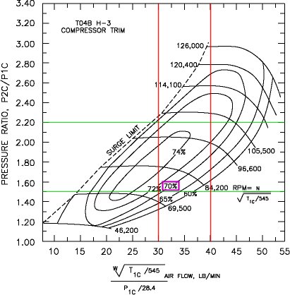
T04B H-trim Let's look at the compressor map that we posted first: the H-trim. The "box" does run into the upper half of the top-most efficiency plateau (74%). In fact, 3/4th's of the box lands within the 70%+ efficiency plateaus - not bad. At it's best efficiency, 74%, boost levels are within the 1.40 to 2.10 pressure ratios - between 6psi and 17psi. So, this turbo was designed for lower boost pressures, as it's best efficiency is centered around 10psi. We know from experience, that this H-trim makes about 300 to 350 hp to the wheels on a DynoJet with very good boost response. If you're going to keep boost levels relatively low around 15psi, this is a very good turbo up to about 350hp at the wheels. The box is completely away from the surge limit line. This compressor wheel is one step down from the 60-1. |
 |
|
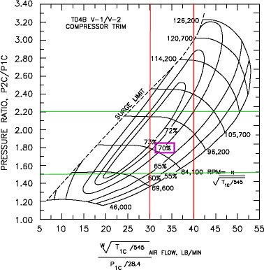
T04B V-trim The V-trim is one step down from the H-trim; we're going progressively smaller. The box is away from the surge limit line - good. Only half of the box is within the 70%+ efficiency plateaus, so efficiency wise it is not a good match for the 13B. A higher boost, it could work okay, as the box would get taller. In our experience, the V-trim is an extremely fast spooling turbo for the 13BT, but it's limited to about 300hp at the wheels on a DynoJet. |
 |
|
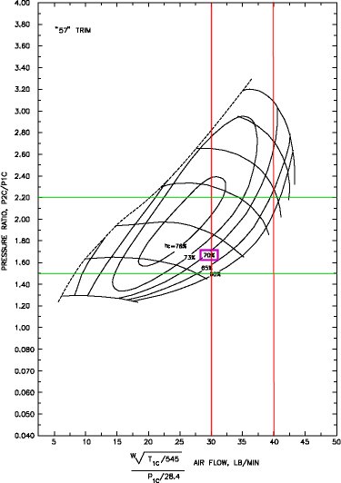
T04E "57" Let's shift now to the T04E turbos. This is interesting as this is similar to the turbo that HKS uses as a "T04E" upgrade for the FC3S. The box is away from the surge limit line. The box is only about 1/3rd into the 70%+ efficiency plateaus, so for low boost it doesn't work too well; at high boost levels, it's a better match. This turbo is starting to get a little too small for our 13B application. |
 |
|
T04E "60" The T04E "60" is one step up from the "57" and is the largest T04E compressor wheel available. This is also one of the more popular compressor sizes for the 13BT. The box easily clears the surge limit line. Over 3/4th's of the box is within the 70%+ efficiency plateaus - very nice. With it's top efficiency plateau over 78%+, the boost ratios are from 1.5 to 2.5, so this compressor wheel is designed to make best power from 7psi all the way up to 22psi - a very wide range of boost. With such good matching for the 13B, no wonder this compressor wheel works very well. Like the 60-1, this turbo can make 400hp at the wheels on a DynoJet. |
 |
|
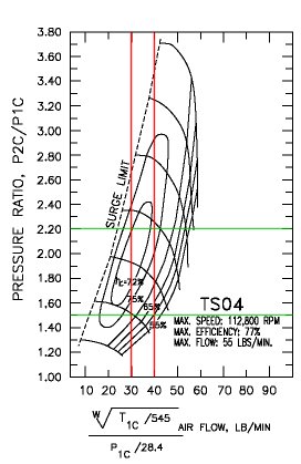
Turbonetics T-58 / TS04 The TS04 is another popular pick for the 13B, and compares with the 60-1 and the T04E "60". Looking at the compressor map, it looks very similar to the T04E "60". The 70% efficiency plateau isn't explicitly labeled, but it's probably the line in between the 65% and 75% lines. Notice that the TS04 goes a lot higher than the T04E "60", so the TS04 can make power at really high boost - 30psi to 40psi+! On a 13B, the TS04 puts up similar numbers like the 60-1 and the T04E "60" - 400hp at the wheels on a DynoJet. |
 |
|
Turbonetics T-66 Let's look what happens when we go bigger than the TS04. The T-66 is a serious turbo with the potential to hit 500 at the wheels. The compressor map shows that the 13B would only be using the low side of the compressor map, but it looks perfectly fine. Others will argue the T-66 is too big, but the compressor map shows that it's a decent match for the 13B. The compressor map is more suited toward higher boost levels, as the peak efficiency is centered around 2.50 pressure ratio or about 22psi. It is a waste to use this turbo under 20psi, but it should move a lot of air on a 13B. |
 |
|
Turbonetics T-76 So what does it look like when we go ridiculously too big? The T-76 is a pretty damn huge turbo, but the compressor map doesn't make it look that bad. Although it's obvious the turbo has more capability than your typical 13B can push, the box skims the bottom edge of the 70%+ efficiency plateaus. What we start to worry about is the box starts to edge into the surge limit line - this is a sure sign the turbo is too large for this application. If you could spool this turbo, we're talking 500 to 600hp! |
 |
|
T3 "60 trim" So what happens when you get too small? The box ends up clearly to the right and outside of the 70%+ efficiency plateaus. This is an extreme case versus the mild case the T04E "57". |
 |
|
Garrett GT35R We'll leave with one last compressor map analysis, the Garrett GT35R. This is fast becoming one of the more popular, high-end turbos. It produces nice results, but it is pricey! Notice, the box goes right through the center of the efficiency plateaus, and it stays all within the 70%+ areas! No wonder this turbo performs so well on 13B applications... |
 |